Folded tray panel + channel letters
Sheet metal face with applied channel letters. Front illumination of the letters; a non-illuminated version can be considered.
Luminous or non-luminous variant depending on the project.
A sign perpendicular to the façade, rectangular, round or custom-cut, to be seen from along the street.
A projecting sign is fixed perpendicular to the façade. Its faces allow it to be read from both directions of traffic. The shape, projection and fixings are designed together.
Choose a sub-family, then the exact product. Then open its mounting submenu to display its assembled 3D plan: at night for lit or backlit products, by day for products without lighting. Then add your selection to the basket or return to the families menu.
← All familiesDouble-sided opaque with structure and façade connection.
Overall projection, two visuals and fixing.
Two diffusing faces and internal lighting.
Light distribution and access.
Circular double-sided box with lighting and fixings suited to the diameter.
Diameter, thickness and power supply.
Two opaque faces in a circular volume, with no lighting equipment.
Outline, visuals and projection.
Specific contour for the logo or project, lit or unlit after assessment.
Vector file, radii and rigidity.
Boxes placed on the faces of the projecting sign, with frontal lighting or opaque faces.
Overall size of the letters and fixing.
Diffusing faces with boxes; backlighting of the backing and letters studied separately.
Allowance for loads and access to both sides.
Cut graphics on both faces and associated with a diffuser.
Direction of the visuals and retention of the diffuser.
Fitted inserts flush with the cut faces for a graphic with no visible protrusion.
Tolerances and removal of elements.
PMMA passing through both faces with a 5 mm projection in front of the sheet metal, illuminated or not.
Projection and retention of the PMMA on each face.
Diffusion on the sides or peripheral light slots, depending on the construction.
Side diffusion and maintenance access.
Shallow depth sought with peripheral lighting and negative graphics.
Achievable depth, diffusion and rigidity.
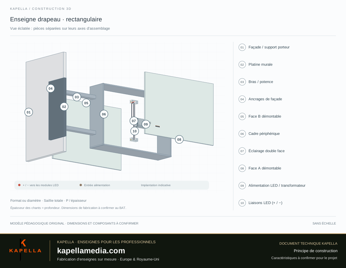
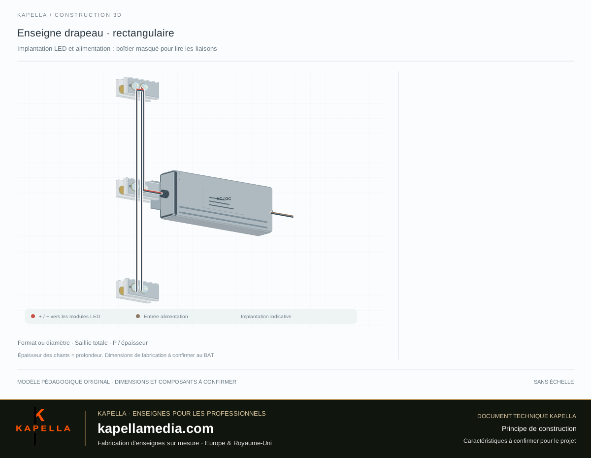
Day and night views, assembled, exploded and open: examine the parts, then activate “LEDs & power supply” to read the routing of the connections and the layout of the modules. The channel letters are shown without an apparent border. The models explain the principles; the manufacturing characteristics are defined for each project.
Select Day or Night to identify the lit areas. Indicative rendering; intensity and colour to be defined. Rotate the model using the control or by dragging it with the mouse. Tap a number or a component in the legend: only one link appears and the part is highlighted.
Its function and the technical points to be specified will appear here.
Example illuminated on both sides. The non-illuminated version is designed without modules or wiring.
| Reference / component | Function and characteristics |
|---|---|
| 01 / Facade / load-bearing support | The support is perpendicular to the two reading faces. Anchorages depend on its nature and condition. |
| 02 / Wall plate | Connection of the arms to the façade. Thickness, shape, welds and drillings to be defined. |
| 03 / Arm / bracket | Allowance for projection and loads. Section, span and assembly according to the project. |
| 04 / Façade anchors | Tiges, fasteners and centres to be determined according to the support, projection and load requirements. |
| 05 / Removable B face | Second face, visual approved separately. Access to components according to the construction. |
| 06 / Perimeter frame | Double-sided volume adapted to the outline. Depth and opening method to be defined. |
| 07 / Double-sided lighting | Optional principle. Positioning, double-sided diffusion and power to be defined. |
| 08 / Removable A face | Visual and reading direction to be identified. Diffusing if luminous version. |
| 09 / LED power supply / transformer | Box, access and ventilation to be provided. Mains input and output to the LEDs marked separately; model and specifications to be defined for the project. |
| 10 / LED connections (+ / −) | The routing of the two conductors follows the modules. The connections are shown for the purpose of understanding the principle; sections, protection and connections are defined in the technical file. |
Download the vector 3D view · Displayed assembly sheet Download the LEDs & power supply view
Validation of the shape and front / back visuals
Cutting of the faces and fabrication of the frame or panel
Preparation of fixings and LED integration if planned
Control, face identification and installation preparation
| Shape | Rectangular, round or custom outline depending on the logo and the desired finish. |
|---|---|
| Dimensions | Width and height, or diameter for a round model. Specify the thickness and the overall projection from the façade. |
| Faces | Two communication faces, with graphics and reading direction to be approved separately. |
| Construction | Solid panel or box, materials, frame and finish depending on the selected version. |
| Lighting | Non-luminous version or integrated LEDs with diffusing faces. Distribution and power supply to be defined. |
| Fixing | Bracket, plate or integrated fixings depending on the construction and the support. Load transfer to be assessed. |
| Layout | Height, overhang, clearance under the sign, wind exposure and local constraints to be examined. |
| Maintenance | Access to the faces, lighting and power supply to be planned for a lit version. |
The width relates to the sign itself. The total projection includes the sign and the distance separating it from the façade: please provide both values if known.
Yes, subject to the chosen construction. Send one file per face and indicate the required reading directions to avoid mirrored graphics.
The vector file is used to assess feasibility. Fine details, radii, dimensions and lighting constraints may require an adjustment to be validated with you.
Photos, the nature of the substrate, the height, dimensions and the desired projection. Brackets and anchors are defined according to the project; insulation or cladding requires an assessment of the load-bearing substrate.
Any site constraints and possible permits must be checked for the project address with the relevant contacts. The drawings on this sheet do not constitute site approval.
To compare quotations on the same basis, please have these elements specified in your request.
| Documents | Proof, validated dimensions, marking-out and any installation template. |
|---|---|
| Assembly | Fixings, stand-offs or mounting rails, quantity and compatibility with the support. |
| Electrical | For illuminated versions: LED, power supply, cabling and scope of connection. |
| Delivery | Packaging, destination, transport, unloading and any handling. |
| Tracking | Care advice, access to components and applicable warranty conditions. |
This list is intended to frame the order: it does not mean that all these elements are systematically included.
The final choice depends on the graphic, dimensions, environment and installation conditions. Materials, processes and finishes are confirmed for each project.
Add this model to the basket +| Shape | Rectangle, circle or custom vector outline |
|---|---|
| Dimensions | Width × height or diameter, thickness and overall projection |
| Visuals | Graphics and reading direction on each face |
| Lighting | Illuminated or non-illuminated, power supply and technical access |
| Fixing | Support, bracket, height and site constraints |
Send the visual, dimensions and site constraints. We will review the technical solution and quotation with you.
View my quotation basketDouble-sided projecting signs, also called blade signs, for sign makers and resellers: round, rectangular or bespoke shapes, illuminated or non-illuminated. Acrylic faces, applied letters and cut-out panels offer different effects. Specify the wall bracket, projection, artwork and fixing requirements in your manufacturing brief.